48v Bldc Motor Controller Circuit Diagram
Brushless dc motor controller wiring diagram – letterlazc Bldc motor controller wiring diagram gallery Diagram wiring motor bldc controller brushless nema dc gems
brushless dc motor - What PWM inputs are needed to drive a 3 phase BLDC
Brushless dc motor Bldc mosfet switching phases works electronics How is high side switching with an n channel mosfet possible in a bldc
Brushless bldc diagram wiring 48v 500w robotdigg
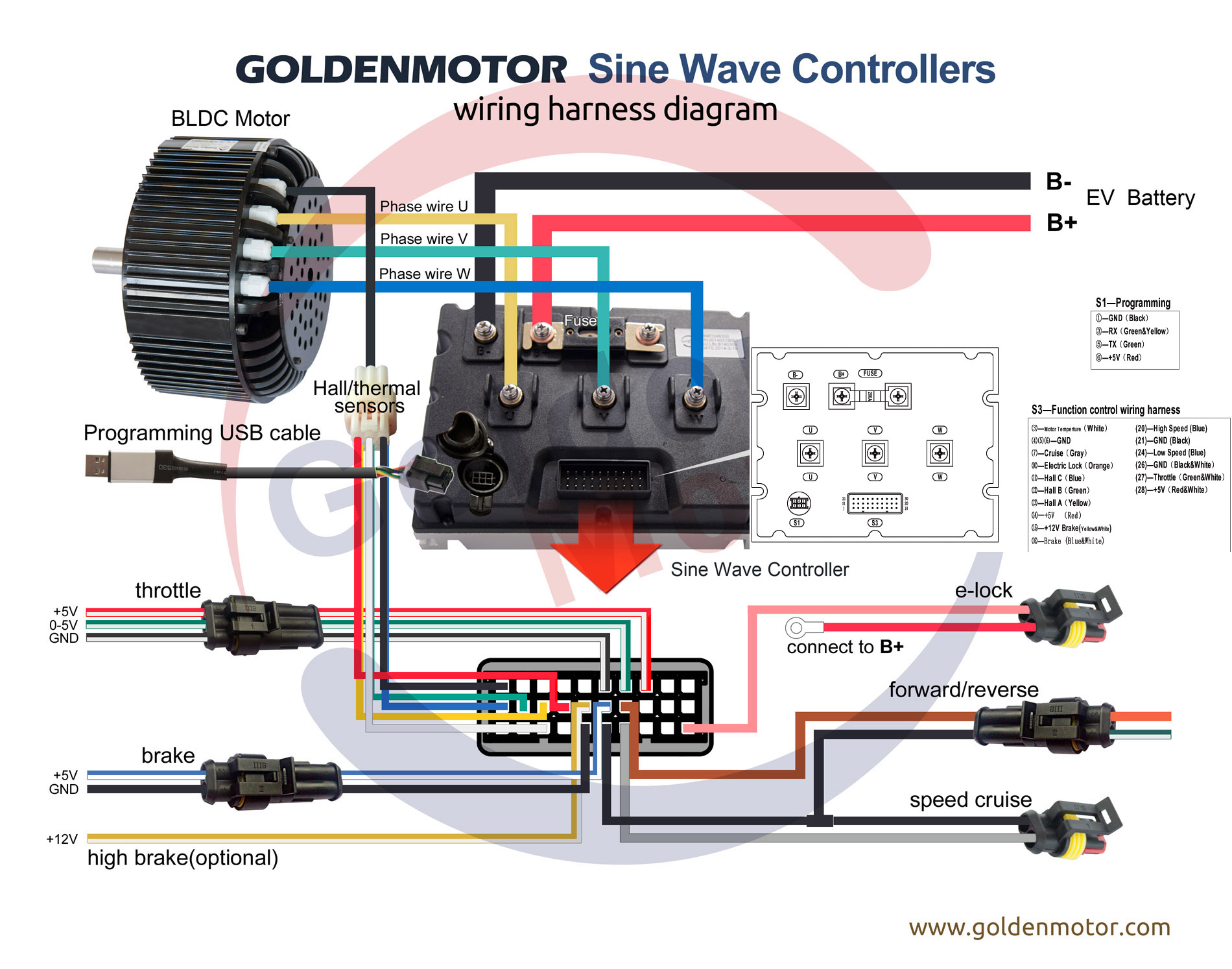
Bldc motor controller wiring diagramWiring bldc brushless goldenmotor controllers sensorless foc elektroroller anschluss golden arduino battery odwiedź Bldc motor driver controller phase ic pwm drive inputs using circuit brushless diagram dc chip pdf hall stack needed microControlling a bldc motor with an esc.
48v bldc motor controller circuit diagramMotor esc bldc controller brushless circuit controlling atmega16 avr diagram dc Bldc motor diagram controller control circuit wiring sensored brushless dc schematic rom cd hall microcontroller sensors speedBldc motor controller wiring diagram gallery.

Motor 48v bldc diagram controller circuit schematic wiring dc role brushless
.
.


How is high side switching with an N channel mosfet possible in a BLDC
bldc motor controller wiring diagram

Controlling a BLDC Motor with an ESC

Bldc Motor Controller Wiring Diagram Gallery - Wiring Diagram Sample

brushless dc motor - What PWM inputs are needed to drive a 3 phase BLDC

Brushless Dc Motor Controller Wiring Diagram – Letterlazc